⚠️ Important: Before proceeding, please read the full Shutter controller - disclaimer. By following this tutorial, you accept that you are doing so at your own risk.
Repository: <a href=https://github.com/pascalweiss/shutter_controller>github.com/pascalweiss/shutter_controller
Introduction
This tutorial will show you how to integrate your roller shutter into your home automation system. With each chapter, we will increase the level of integration. Since every chapter will provide an applicable result, you don’t have to finish the whole tutorial. But if you you do, you will have a fully integrated roller shutter, that can be scheduled via Home Assistant. You will be able to automatically set the shutter to a certain level at a certain time. See the following example:
Example: My own Shutter Automation
- In the evening it automatically closes at sunset time.
- In the morning the shutter is opened to 50%. So we can wake up with sunlight.
- 2 hours later - when everybody left the home - it is opened fully.
Additionally I can always set the shutter level manually with a poti controller, that is mounted to the wall.
Basics: Shutter motors
The only requirement for automating your roller shutter is a tubular shutter motor that is installed in the shutter axis. Despite of the neutral- and the ground conductors, there are two phase conductors. One for moving the shutter up- and one for moving it down. By applying voltage on one of these phases, the motor starts rotating with constant speed in the corresponding direction. (We will use this fact for estimating the current state of the shutter at Integration Level 3).
Integration level 1: Control the shutter with a remote switch
This is the first step in this tutorial. We will now connect motor with a radio receiver and control it with a remote switch. This step will also provide the foundation for further integration in the subsequent sections.
Required hardware components:
- 433Mhz receiver Receives commands via 433 Mhz and controls the motor with relays
- 433Mhz remote switch Sends commands via 433 Mhz to control the motor.
We begin by connecting the 433Mhz receiver to the motor. As described in the basics section, the motor has two phase wires (one for UP, one for DOWN), a neutral- and a ground wire. Caution: Before working on the wires, turn off the power! Now each of these wires can be connected to the receiver by attaching it to the corresponding socket in the green area (see image). The sockets in the blue area can optionally be used for applying a manual wall switch.
When every wire is connected (and isolated), we can turn on the power, again. Finally you have to couple the remote switch to the receiver by pressing the connect button - the LED starts flashing - , and by pressing one of the “ON” buttons on the remote. The coupling was successful, when the LED on the receiver stopps flashing.
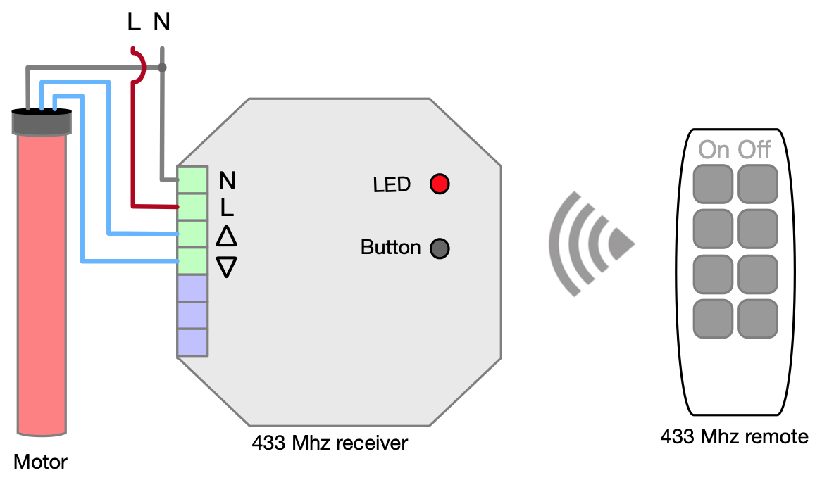
When everything is set up correctly, you are now able to control the motor with the remote. By pressing either ON or OFF on the remote you will hear the clicking of a relay, and the motor will start moving in the corresponding direction.
Integration level 2: Control the shutter with an arduino and a poti
Having a remote switch for controlling the motor is already a useful solution. Still there are some drawbacks: First: the remote can’t be integrated into an automation system. And second: For setting the shutter to a certain height, we have to do this manually by pressing and releasing the button for the right duration. We will now solve this problem by replacing the remote with an Arduino and a 433 Mhz sender. Additionally we will add a poti for setting the desired height of the shutter.
Required Hardware Components:
- Arduino microcontroller By uploading our own custom C programs, we can send/read data via GPIO. First we’ll use it for sniffing the commands from the remote, then we’ll use it for controlling the shutter.
- 433 Mhz sender Used by the Arduino for sending 433 Mhz commands to the receiver.
- B10k Linear Potentiometer We’ll use this to set the desired height of the shutter.
But before we can start, we have to do some preliminary work.
Sniffing radio commands with Arduino
For replacing the remote we have to imitate it by sending the same values. Therefore we will now build a little radio sniffer. This is done as follows:
- Connect your Arduino via USB and make sure that everything is set up properly, so that you can compile and upload your own sketches to the micro controller. If you have problems here, you can follow e.g. this tutorial https://www.arduino.cc/en/Guide
- Install the library RCSwitch. You can do this inside the Arduino IDE with the ‘Library Manager’.
- Connect the D2 connector with the data connector of the 433 Mhz sender. Also connect VCC to 5V, and GND to GND (see the following schema). Note: You may want to use jumper cables for the wiring, since you might want to reuse the Arduino as remote controller in the next step.
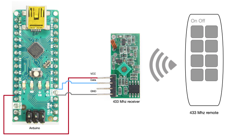
- Now that everything is wired up, we install the sniffing software on the Arduino. Copy & paste the following code into the IDE or open the file in the repository (see above).
#include "RCSwitch.h"
#include <stdlib.h>
#include <stdio.h>
RCSwitch mySwitch = RCSwitch();
void setup() {
 Serial.begin(9600);
 mySwitch.enableReceive(0);
}
void loop() {
 if (mySwitch.available()) {
 int value = mySwitch.getReceivedValue();
 if (value == 0) {
 Serial.print("Unknown encoding");
 } else {
 Serial.print("Received ");
 Serial.print( mySwitch.getReceivedValue() );
 Serial.print(" / ");
 Serial.print( mySwitch.getReceivedBitlength() );
 Serial.print("bit ");
 Serial.print("Protocol: ");
 Serial.println( mySwitch.getReceivedProtocol() );
 }
 mySwitch.resetAvailable();
 }
}- Compile and upload the sketch to the Arduino.
- In the Arduino IDE, open the Serial Monitor and press the “ON”, “OFF” buttons on the remote.
- The monitor should now print the received values from the remote. In my local example this looks as follows:
21:23:06.515 -> Received 2821412352 / 32bit Protocol: 2
21:23:07.184 -> Received 2687194624 / 32bit Protocol: 2- Convert these values into binaries. You can use some online converter for this. The resulting values should be 32 bit numbers. E.g. 2821412352 becomes 10101000001010110101011000000000
Voilà! Now we know the commands for remote control of the motor. Write them down! You will need them in the next step. If you don’t want to reuse the sniffer for another shutter later, you can now disassemble it (this is why you should use jumper cables).
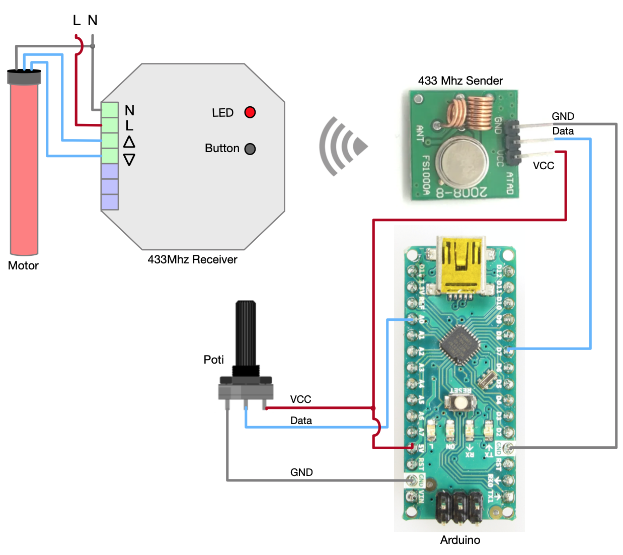
Build a poti-controlled, programmable 433 Mhz sender
Before we install the final software on the Arduino, let us first set up the hardware. Connect GND to GND and VCC to 5V for both, the poti and the sender. Also connect the data connector of the sender to D7 and the remaining poti connector to A0. See the sketch for an example:
Installation and callibration of the software
The final step in this section is to install the software, and to provide some configuration values.
- Clone my github project to your local machine
git clone https://github.com/pascalweiss/shutter_controller.git- Open the
shutter_remote_controller/shutter_remote_controller.inoin Arduino IDE. - Open the tab
config_rf433.h - Assign the binary numbers that you sniffed previously to the variables
RF433_UPandRF433_DOWN.
The resulting config_rf433.h should look similar to this:
...
// set this to the corresponding digital pin
byte PIN_RF433 = 7;

// The value that is sent for moving the shutter up.
// You have to sniff it from a remote control
#define RF433_UP "10101000001010110101011000000000"

// The value that is sent for moving the shutter down.
// You have to sniff it from a remote control
#define RF433_DOWN "10100000001010110101011000000000"
...- Measure the required time for opening and closing the shutter completely
- Assign the values to the variables
SECS_ROLL_UPandSECS_ROLL_DOWNinconfig_application.h
Note: The file config_application.h provides many other configuration properties, that you might have to adjust.
Explaining each of these properties would require to explain the whole algorthm.
This would exceed the scope of this tutorial and it is likely that the default values will just work.
But if you do have to adjust the other configuration properties, the code documentation provides some hints.
Congratulations! You just built your own remote shutter controller. This set up is already quite useful since controlling the shutter with a poti is much more convenient than pressing a button for a certain amount of time. If you are not interessted in further integration you can now install your Arduino remote in a plastic box and mount it to the wall (maybe next to the light switch). Otherwise, if you want to integrate the Arduino with a raspberry pi and Home Assistant, you will have to add another communication module to the Arduino. So you might want to wait with installing your device into a plastic box.
Integration Level 3: Control the Shutter with a Raspberry Pi and Python
In this step we will set up a little single-board computer - a Raspberry Pi - and integrate it with the Arduino. We will set up a little flask server that is able to send a desired shutter height via an NRF24 module. The server itself will receive commands via a REST API. So in the end, the motor will be controlable over the network with http.
Required Hardware Components:
- Raspberry Pi mini computer A little computer that is mainly used for DIY projects and education. It is cheap, consumes low amounts of power and provides GPIO for connecting low-level hardware componets. We will use it for sending data to the Arduino, and for hosting Home Assistant.
- NRF24L01 transceiver Communication module for sending/receiving digital data. We will use it for sending the target shutter height from the Pi to Arduino.
- SD Card Used as disk for the Raspberry Pi.
Some system prerequisites
- The Raspberry Pi should the raspbian linux distribution. You can install this by flashing the SD-Card with the newest raspbian version. Instructions on how to do this are plentiful available on the internet.
- Since NRF24 use SPI, we have to enable it on the pi. Therefore we have to start up the Pi and execute
sudo raspi-config - There you should go to
Interface-Options > P4 SPIand enable it - Also we have to expand the filesystem here
Advanced Options > A1 Expand Filesystem - Finally go to
savethe Pi should reboot now, automatically.
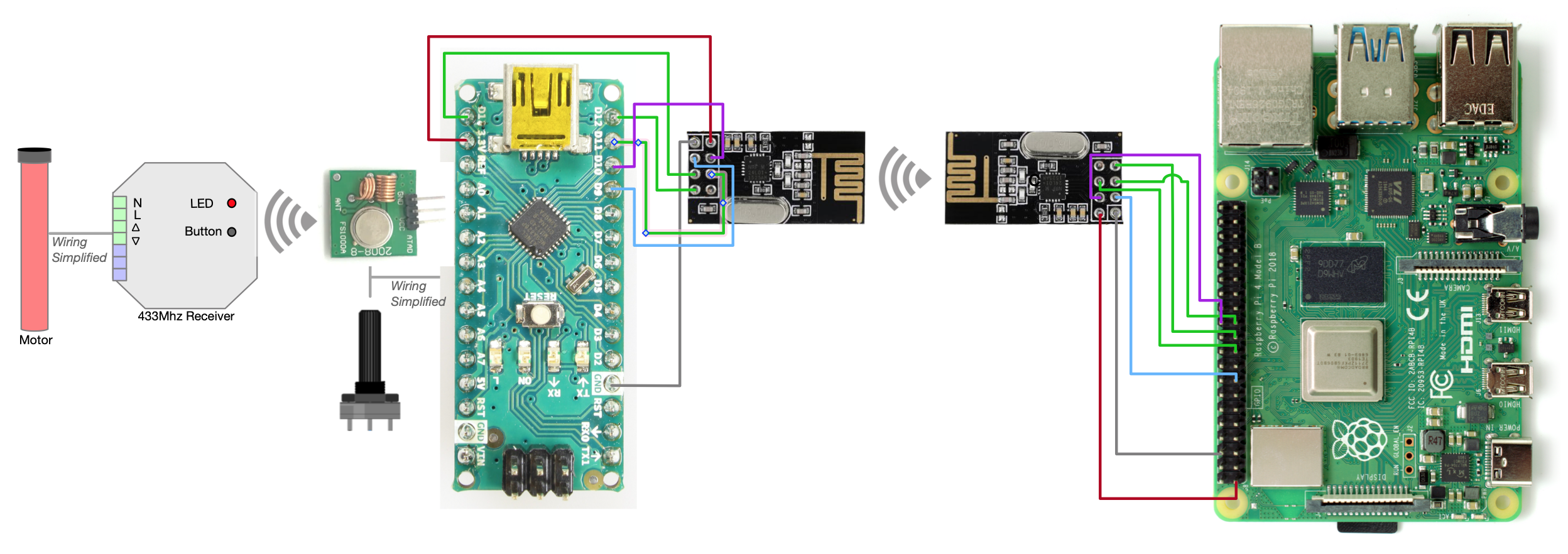
Wire up NRF24 Transceiver with Arduino and Pi
First we have to wire everything up. The NRF24 has 8 connectors from which 7 have to be connected to both, the Arduino and the Pi. The exact wiring is visualized in the following schema, as well as in the following table.
| NRF24 | Arduino Nano | Pi 4 |
|---|---|---|
| VCC | 3.3V | 3.3V (e.g. 1) |
| GND | GND | GND (e.g. 6) |
| CSN | D10 | GPIO7 (26) |
| CE | D9 | GPIO22 (15) |
| MOSI | D11 | GPIO10 (19) |
| SCK | D13 | GPIO11 (23) |
| IRQ | - | - |
| MISO | D12 | GPIO9 (21) |
Install NRF24 library for Arduino and Raspberry Pi
Now we will install the library on Arduino and Raspberry Pi. There are various libraries available for the NRF24. Since they don’t seem to be compatible to each other (at least not for communication between Arduino and Raspberry Pi), we have to make sure to use the libraries from the same project. I had good results with TMRh20s libraries. For installing, do the following:
- On the Raspberry Pi, install the NRF24 library with python-wrapper. The library has to be compiled on the Pi. So this will take some time. Instructions for the installation can be found here: https://nrf24.github.io/RF24/Python.html
- In the Arduino IDE, you should find TMRh20s NRF24 library in the ‘Library Manager’.
Now you should be able to exchange data from the Pi to the Arduino and the other way around. Various examples can be found here https://nrf24.github.io/RF24/examples.html and are well described on other parts of the page, or on blogs like https://tmrh20.blogspot.com/.
Install a flask server for controlling over http
Now that we have set up the NRF24 tranceiver we will now use it for controlling the shutter. After this step we will have a little flask server on the Pi, that is able to receive a desired shutter heigt via http GET requests. The server will then send the desired shutter height via NRF24 to the Arduino. Similar to a changed value with the poti, the Arduino will then control the motor over 433 Mhz radio commands and set the desired height. We will also ensure that the flask server started at boot up. So every time you power up the Pi, the server will be available. So let’s see how to do this step-by-step.
The project is written in python3. This should already be installed on your Pi. If not, do
sudo apt update
sudo apt install python3-pip
To check if everything worked, you can do
pip3 --versionAs you did before when you set up the Arduino, we will now clone the project again on the Pi.
git clone https://github.com/pascalweiss/shutter_controller.gitNow navigate to the project and install the requirements.
cd <path-to-repo>/shutter_controller/shutter_remote_api
pip3 install -r requirements.txt
Now you should already be able to start up the server with python3 api.py and send control requests.
But since we want to start up the server automatically on every boot, we have to set it up as a systemctl service:
Create a new service in /etc/systemd/system. You can do this with your favorite editor, like:
sudo vim /etc/systemd/system/shutter_remote_api.serviceThen write the following code into the file:
[Unit]
Description=REST api for sending commands to the shutter controllers via RF24

[Service]
Type=simple
ExecStart=/usr/bin/python3 /home/pi/dev/shutter_controller/shutter_remote_api/api.py
[Install]
WantedBy=multi-user.target
Now reboot your Pi. When it is up again, the new service should be running. You should be able to print its logs with
sudo journalctl -u shutter_remote_api.serviceHere you should get some output like:
Mar 30 19:32:35 raspberrypi systemd[1]: Started REST api for sending commands to the shutter controllers via RF24.
Mar 30 19:32:40 raspberrypi python3[391]:  * Serving Flask app "api" (lazy loading)
Mar 30 19:32:40 raspberrypi python3[391]:  * Environment: production
Mar 30 19:32:40 raspberrypi python3[391]:    WARNING: Do not use the development server in a production environment.
Mar 30 19:32:40 raspberrypi python3[391]:    Use a production WSGI server instead.
Mar 30 19:32:40 raspberrypi python3[391]:  * Debug mode: on
Mar 30 19:32:40 raspberrypi python3[391]:  * Running on http://127.0.0.1:8081/ (Press CTRL+C to quit)
...
If you get similar logs, you are done now. When the Arduino is set up as previously described, you should now be able to set the shutter hight via http. E.g. you could do a curl command as follows (note that the height is provided as percent in a json):
curl localhost:8081/setShutterLevel --data '{"level": 0.64}' --header "Content-Type:application/json"Integration Level 4: Control the Shutter with a Raspberry Pi and Home Assistant
This is the last step to the full integration of the remote controller. Instead of manually sending http requests (like in the previous example) we will now finally install Home Assistant. This will not only provide a nice UI for controlling the shutter, it will also provide the ability to scheduling control commands. Therefore we can use various triggers like sunrise/sunset or weekdays and time. In the following steps we will configure Home Assistant similar to the setup described in the introduction:
- We will open the shutter on weekdays at a certain time
- We will close it at sunrise.
Home Assistant Installation
Of course we first have to install Home Assistant on the Raspberry Pi. The Home Assistant documentation describes various ways for installing the software. Since I want to use the Raspberry Pi for other things as well (like the flask server), I chose to install the software as a docker container. A guide on how to do this is provided here <a href=https://www.home-assistant.io/installation/raspberrypi>home-assistant.io/installation/raspberrypi
Home Assistant Configuration
Now that we have a running Home Assistant deployment, we can configure it for controlling the shutter.
- Add the following services to
<path-to-homeassistant/config/configuration.yaml
rest_command:
  open_full:
          url: "http://localhost:8081/setShutterLevel"
          method: "post"
          content_type: "application/json"
          payload: '{"level": 0.0}'
  open_half:
          url: "http://localhost:8081/setShutterLevel"
          method: "post"
          content_type: "application/json"
          payload: '{"level": 0.5}'
  close:
          url: "http://localhost:8081/setShutterLevel"
          method: "post"
          content_type: "application/json"
          payload: '{"level": 0.65}'
binary_sensor:
  - platform: workday
    country: DE
    workdays: [mon, tue, wed, thu, fri]
excludes: [sat, sun]- Add the following scripts to
<path-to-homeassistant/config/scripts.yaml
open_shutters_full:
  alias: open shutters full
  sequence:
  - service: rest_command.open_full
  mode: single
  max: 10
open_shutters_half:
  alias: open shutters half
  sequence:
  - service: rest_command.open_half
  mode: single
  max: 10
close_shutters:
  alias: close shutters
  sequence:
  - service: rest_command.close
  mode: single
  max: 10
- Add the following automations to
<path-to-homeassistant/config/automation.yaml
- id: '1615669286832'
  alias: Open shutters half
  description: ''
  trigger:
  - platform: time
    at: "06:30:00"
  condition:
    condition: state
    entity_id: binary_sensor.workday_sensor
    state: "on"
  action:
  - service: script.open_shutters_half
  mode: single
- id: '1615669286852'
  alias: Open shutters full
  description: ''
  trigger:
  - platform: time
    at: "07:45:00"
  condition:
    condition: state
    entity_id: binary_sensor.workday_sensor
    state: "on"
  action:
  - service: script.open_shutters_full
  mode: single
- id: '1615669378243'
  alias: Close shutters
  description: ''
  trigger:
  - platform: sun
    event: sunset
  condition: []
  action:
  - service: script.close_shutters
mode: single- Now open the Home Assistant overview in the browser
<ip-of-the-raspberry>:8123/lovelace/default_view - In the three-dot menu on the top right, click “Edit Dashboard”.
- The click ”+ Add Card” on the bottom right and choose “Manual” on the bottom of the list
- Paste the following yaml in the txt field
type: entities
entities:
  - entity: automation.open_shutters_half
    name: Open half in the morning
    secondary_info: last-triggered
  - entity: automation.open_shutters
    name: Open full in the morning
  - entity: automation.close_shutters
    name: Close at sunset
    secondary_info: last-triggered
  - entity: script.open_shutters_half
    name: Open half now
  - entity: script.open_shutters_full
    name: Open full now
  - entity: script.close_shutters
    name: Close now
title: Rollladen
This will provide the following card to you:
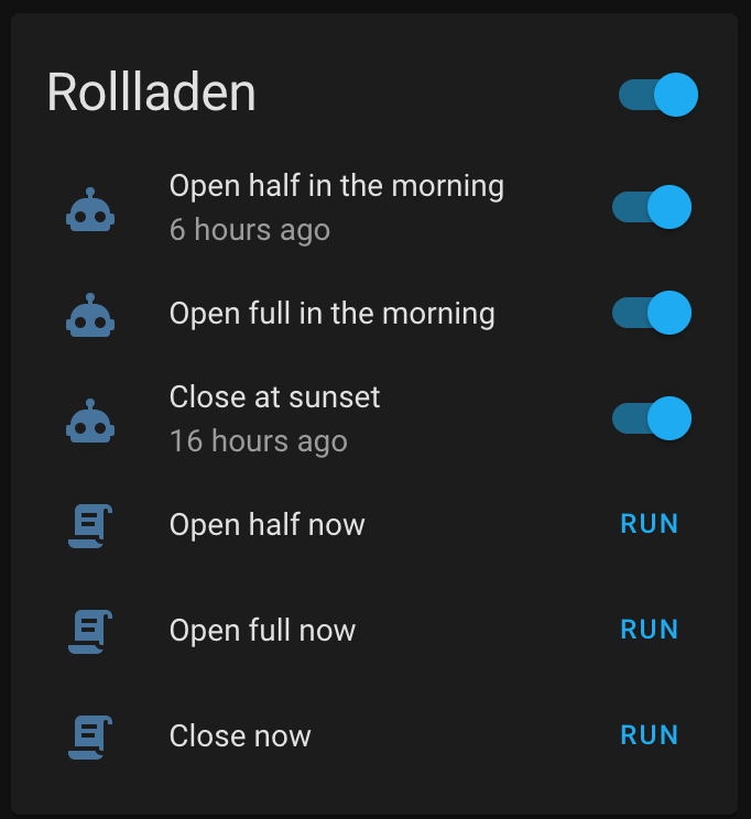
By clicking enabling the switches you can turn on/off the various automations. You can also execute the commands manually by clicking on “Run”. If you want to change the parameters, e.g. for the automation, you can do this easily by editing the .yaml files. You may also want to create your own automation.
Congratulations, you have now finished the integration of the shutter controller.
06.05.21